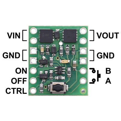
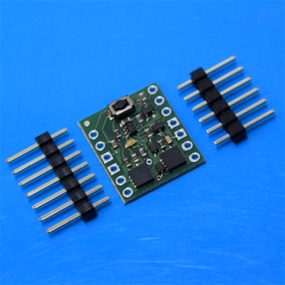
Momentary to latching converter 2.2 to 16V
Allows for the use of a momentary switch in a latching circuit.
Specifications
•Dimensions: 0.6" x 0.7" x 0.12" (without header pins installed)
•Operating voltage: 2.2-16V
•Maximum current: 6A
•Draws very little current in off state (typically under 0.01 μA)
-
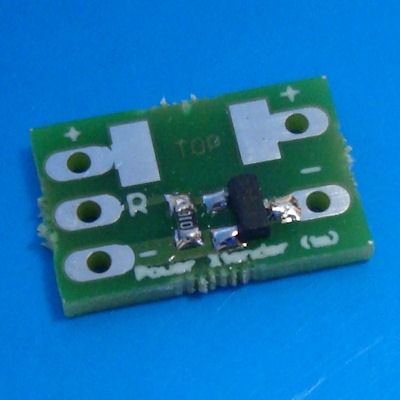 Plecter Labs Power Xtender™ Ver 2.0 Miniature electronic circuit designed to drive/switch a high load (LED, rumbling motor, relay) when the low voltage/current output from our electronic boards does not allow it. Drives for instance a 3.6V LED from a Blaster Core™ board or a luxeon from the Flash on Clash™ output of Crystal Focus™. Refer to the Petit Crouton user's manual for further details about the use of this module. NEW : Now with embedded SMD 2512 resistor footprint. Saves space when using the Power Xtender™ to drive the Flash On Clash ™. Use with 2 watt 2512 thick carbon film resistor. Dimensions : 0.55"x0.36" Input voltage : 0-5 volts max. Switches at 3.3V Output voltage/current : 12V / 1.5A
 -
Out of stock
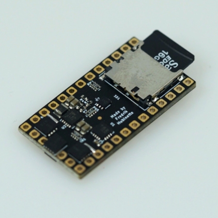
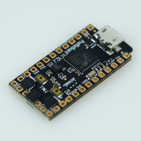 All-in-one STM32L4-based lightsaber electronics. It is small, feature-packed and 100% open source. This board retains all the features from the Teensy based designs, but are smaller and requires less work to put together. These are more advanced boards to use and it is recommended to read the detailed manual before use. Listing includes 1 x Proffieboard v2.2 and 1 x Micro SD Card. This is a new board with rolling updates. Board information and diagrams can be found here. These boards have been improved since the v1.5 and now has:Proffie Boards are both factory & SCF tested and confirmed 100% working prior to packing and shipping. When purchasing and installing a board, the customer does so at their own risk. Refunds will not be made for 'bricked' boards.
- Breadboard compatible, no more tiny soldering pads
- Same size as before (1.3 x 0.7 inches)
- BATT- and GND are bridged by default (the bridge can be cut if desired)
- The components are a little farther away from the soldering pads
- The SD card sticks out more than before, hopefully making it easier to grab.
- FET pulldowns are grouned to BATT-, not GND
- Reverse polarity protection
- Beefier 5v power supply
- Able to completely cut power to the SD card (this *should* make deep sleep possible)
- The SD card power is also available on a pad, which could be used to cut power to bluetooth and displays during deep sleep.
- Uses resistor arrays to cut down on the number of components
- One less pad for neopixel data
- Neopixel LED Strip and Tri Cree LED Support.
- 44/22/11khz Audio.
- Touch Button Support.
- Multiple Blades And Effects With Different Presets For Each.
- Supports Both Monophonic and Polyphonic Sound Fonts
- Can Play Background Music With Other Sounds.
- Many Free Pins That Can Also Be Programmed For Other/Additional Features.
- Supports SmoothSwing! The Most Realistic Motion Algorithm For Sabers To Date!
- BATT+ – 2.6 to 4.5 volt input, drives everything except the LEDs
- BATT- – negative pad for LEDs, needs to be at same level as GND when both are connected. Note that there are two of them, which can be useful when driving many powerful LEDs.
- GND – ground for electronics except LEDs. Note that the two GND pads are interchangable and connected through the board.
- Button 1/2/3 – Hook up to closing buttons, or potentially touch buttons.
- Data 1 / ID – Normally used to measure the blade ID restor, and if it’s a neopixel blade, feed out neopixel data. For a fixed non-neopixel saber, it could be repurposed. Note that this pin has an internal 470 ohm resistor on it, so when hooked up to a neopixel blade, it does not need any resistors.
- Data 2-3 – additional neopixel data outputs, or free for other purposes.
- Data4/Dac – noeopixel data output, free, or audio DAC output
- LED 1-6 – Hooks up to negative side of LED (positive side of LED hooks up directly to battery.) These pads can handle up to 30 volts.
- SD Power – FET-controlled 3.3v. can be used to power down bluetooth and displays in low-power mode.
- SDA, SCL – these pins are used to communicate with the gyro and accelerometer chip.
- 5v – generated by the proffieboard, normally it’s only on when sound is playing.
- 3.3v – generated by the proffieboard.
- SWDIO, SWDCLK – can be hooked up to a ST-LINK device and lets you debug programs running on the proffieboard.

